LG301: Arduino Uno
Let's Get Physical
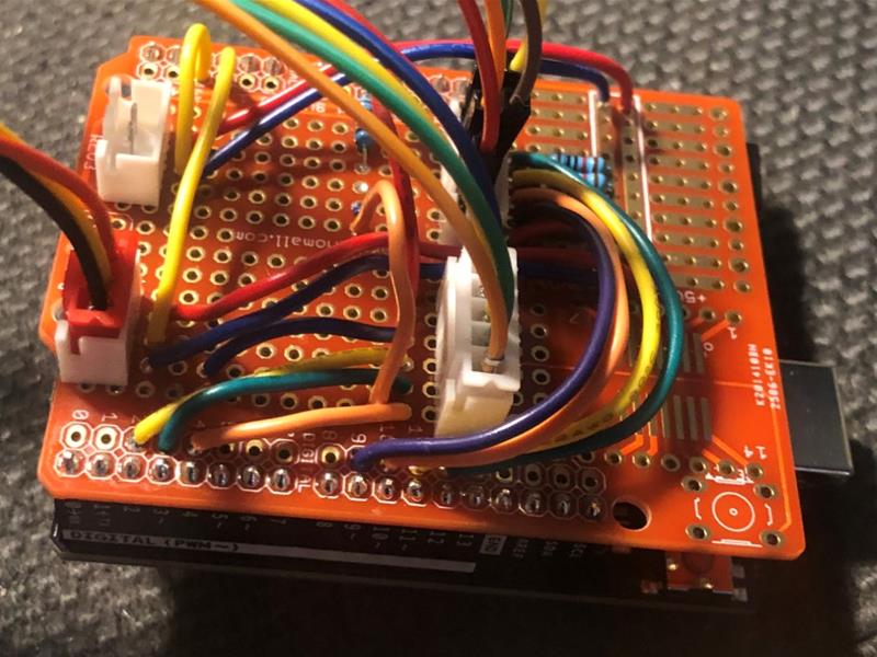
We are going to be asking a lot of the Raspberry Pi so let’s unload controlling the physical inputs and lights to a microcontroller. My usual choice is the ESP32 but we have loads of room, plus the ESP32 doesn’t play nicely with NeoPixels. A big old Arduino Uno with a ProtoHAT so we can put a load of JST terminals on it to keep the wiring tidy and plug and play.
We are going to need to communicate with the raspberry pi and we are going to need some power, so let's just use a USB port, this also enables us to update the sketch without unplugging anything.
There’s just about enough room on the ProtoHAT but things are a little cramped, I’m breaking the NeoPixel control out onto another Perma-Proto Board. We’ll pass the two NeoPixel channels and earth from the Arduino, get a fresh 5v power supply from our 18v input, add a capacitor to keep the pixels smooth and we’ll add a USB power socket for the HDMI screen as we have room. This will help keep the load off the Raspberry Pi.
Power Management
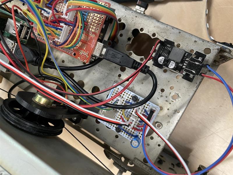
The original radio had a cardboard back and 240v, I electrocuted myself putting a relay in a coffee grinder, and I’ve tried to avoid high voltages since then. The HiFiBerry Amp 2 has a power input socket and likes between 12-24v, it supplies the Raspberry Pi with a steady 5v so we could just plug straight in here but we won’t.
One of our potentiometers, the one we are going to use to control the brightness of the NeoPixels, also has a beautifully ‘clunky’ On/Off mechanism. We’ll run our power supply through this and then to the Amp.
Let’s run the Amp at about 14v as we have a couple of pretty big speakers, between the input and the Amp we’ll add an Adjustable Power Voltage Regulator for two reasons. It's much easier to get an 18v power lead, and we can dial the power down if the speakers sound like they are 'on eleven'.
We’ll also connect a 5V 5A Power Buck Module to the Adjustable Power Regulator to give us the power supply for the NeoPixels and HDMI Screen.
JST Connectors and Sockets
These are great! Hardwire the sockets onto the Perma-HAT and you can plug and plug everything without having to remember where all your breadboard wires have fallen out from.
There’s no going back after making these, however, the guy below makes it look easy… my success rate started at about 30% and is maybe at 60% after crimping all the leads in this project. Old eyes and big hands are not our friends in this instance
A Little C++ Super Loop
This should be simple as we are unloading the complex logic of running services and an interface to a sophisticated multi-threaded programming language, right?
Yep right… This sketch basically sends strings over serial to the Raspberry Pi, and changes the colour and brightness of the lights based on 4 inputs. Easy, except one of the inputs is a clunky 4 position switch with really bad bounce (see LG201) and another is a Rotary Encoder.
Luckily Simon Merrett has done a fantastic piece of work on rotary encoders which I’ve happily included, this implementation was made even easier by the fact we only need to know if the last direction was left or right, we don’t need to keep track of the count… we’ll deal with that Front-End.
Serial communication is currently one-way, future scope would include sending commands from .Net back to the Arduino to change setting such as light colours and to use the lights to illustrate loading and error states.
The Potentiometer Problem
The device uses two potentiometers, one for NeoPixel brightness and one for the Tuner. The potentiometer is connected to an analogue pin and returns a value between 0 and 1024 depending on how much resistance is applied with the dial, Arduino has a lovely map command as illustrated below:
brightnessLevel = map(analogRead(brightnessPin), 0, 1024, 0, 255);

radioStation = map(analogRead(tunersPin), 0, 1024, 0, 20);
Which would be wonderful, if as I presumed, potentiometers were linear…
...they’re not, as the European Passive Component Institute explains and illustrates here in some detail.
We have two problems here, both quite different.
The Brightness button seems a bit non-responsive to lower changes at both ends of the range, compounded by the fact it’s hard to visually identify changes near the brighter end. A solution is to limit the output range of the map statement to the lower end of the brightness spectrum but with 3 colour values being individually altered by a brightness reading you can visually see the colour change on low brightness settings.
The Tuner is a bigger problem, we get to what should be the third station before the reading rises above zero. We get our 20 stations in, but not in the linear divisions indicated on the dial.
There are solutions, we can predefine the points of division, and we can predefine the output colours. we can increase the distance the needle travels, so we tune past both ends of our dial, and we can predefine the 20 channel ranges. This was just a time rabbit hole I wasn’t willing to go down during this module. But I can’t tell you how much leaving it pains me!
The sketch is in the Repo link below, and I’ve added helpful annotations including which bits of code I can’t take any credit for!