LG201: IoT Prototype Development - Electronic Circuits
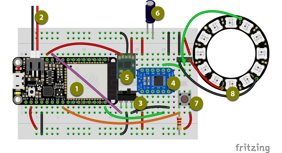
There is usually something bashing around in my bad that looks somewhat like the diagram below but probably broken, there's probably a jumper lead or resistor missing and I probably can't work out why it’s not working just by looking at it. As I pointed out in my introduction, this is the problem I need to solve, this is my requirement.
I produce my code for web-based systems in Visual Studio, in Visual Studio you press the green button and it runs your code, this is how we test. If it opens in the browser and runs, it's passed… you cant do this in Arduino IDE unless you have a board connected.
As Kent Beck points out in the Theory of Constraints section in his book, “work piles up in front of a constraint”, [1] my constraint is not having a device to plug into my laptop that I can run my tests against.
This specification below is a very useful device for testing my code, it has inputs and outputs and will give me a visual indication if things are working. Let’s get this Thing built and then we can keep it safe in a case.
1a Specify Components
Here’s a list of the component I’m going to be using.
-
Adafruit HazzahESP32 – The ESP8266 was a great micro-controller for hobbyists building IoT devices, the ESP32 is the next generation with added Bluetooth support, built-in security features and pretty much everything upgraded. The Adafruit version has a slightly narrower form factor than most the development boards, and added power management features. A great basis for my device, I’d be surprised if I move away from this board over the next few modules, this has graduated from hobbyist to production-ready micro-controller.
https://learn.adafruit.com/adafruit-huzzah32-esp32-feather/overview -
3.7v Battery (2000mAh Lithium Polymer) – I love these batteries flat, powerful and safe. This will enable me to use the device disconnected to test functionality, producing between 4.2v and 3.2v during its working cycle, we’ll need to step that up to 5v, for some of the breakout boards, when the board isn’t connected to USB.
https://www.adafruit.com/category/574 - SPDT Slide Switch – “Have you tried turning it off and back on again?” As this has a battery, we need to be able to turn it off, the Hazzah board helps with this but my requirement for 5v power means we have a little more work to do… See the Power Management section below.
-
I2c Voltage Shifter – The Neopixels and some of the i2c components I plan to use over the next few modules require 5v power and logic. Running a 3v into one side and a 5v into the other will convert the logic level in either direction.
https://www.sparkfun.com/products/12009 -
5v Step-Up - The BAT pin on the Hazzah gives us the charging voltage (4.4v) when the device is plugged into USB and the Battery voltage (4.2v – 3.2v) when disconnected. This nifty little breakout will change that into a steady 5v for the high voltage side of our circuit.
https://www.pololu.com/product/2119 - Capacitor (1000 µF, 6.3V) – NeoPixel best practice says to use a capacitor to buffer sudden changes of voltage drawn by the strip. This will keep our 5v logic steady as a rock too.
- Tactile Switch – Our only physical input, headless devices are great but sometimes you need to be able to reset things manually. Plus it’s a great way of checking functionality whilst working offline.
-
NeoPixels – Our only physical output, but what an output… 3 pins, any number of LEDs in any number of colours. Even one of these can pulse, flash, change colour all the feedback we are going to need.
https://learn.adafruit.com/adafruit-neopixel-uberguide/best-practices - BME280 Barometric sensor (not shown) – This could be anything at this point, to be honest, I just need to send some data to the internet. This gives us the temperature, humidity and barometric pressure. Data is data, if we can gather this we can gather anything?
Power Management
The 3-pin slide switch plays a major part in this circuit as it performs two tasks at the same time. The common pin is wired to the ESP32 Ground and the two circuit pins wired to the Shifter Ground and the Enable Pin on the ESP32, so one circuit is broken whilst the other is live.
Grounding the EN pin disables the 3.3v Regulator on the ESP32 whilst un-grounding the Shifter and breaking the 5v circuit driven by the Step-Up. Swapping it enables the 3.3v Regulator turning on the board, and grounds the 5v circuit. Without this double function, the Battery/USB power was still live on the 5v side of the board, the NeoPixels were pulling current even without a signal from the board.
The built-in power management is useful during development, as it means we can charge the battery whilst using the serial interface to programme the board, but as you’ve seen we have needed to add the Step-Up to achieve our 5v logic.
In final production where no Serial access is required, it would make more sense to deal with voltage and charging before powering the circuit, something along the lines of the functionality offered by the Adafruit Power-Boost breakout.
Security
In their article Modelling trust dynamics in the Internet of Things, Fernandez-Gago, Moyano & Lopez highlight one of the major obstacles facing IoT developers. As they state “It is expected that the ‘things’ involved in the IoT paradigm will have to interact with each other, often in uncertain conditions. It is therefore of paramount importance for the success of IoT that there are mechanisms in place that help overcome the lack of certainty. Trust can help achieve this goal.” [2] They go on to propose a Trust Management System that device manufacturers would sign up to.
Whilst this is beyond the scope of this module, there are interesting points raised that affect the hardware we should work with. I spent a year working on security for a system that would contain the most personal of data, I lost sleep over this whilst researching the answer.
The one weakness that struck me in all systems, was access to source code. If you could access and change the source code, then you could probably access data. With IoT devices, we literally give the customer the source code, if you can get the code of the Flash you can work out how any Key was created.
Articles like Data Security in Cloud Computing with Elliptic Curve Cryptography [3] explain the methodology and A secure inter-domain communication for IoT devices [4] highlight why the ESP32, with its built-in cryptography hardware, is a good contender for IoT development.
However, for me, the two most powerful features of the ESP32 are Flash Encryption [5] and Secure Boot. [6] These not only deny the owner access to the source code but effectively, once implemented, stop the device being written too again. There’s a simple explanation of these feature in Understanding ESP32’s- Security Features, [7] on Medium.
Once you have denied access to source code, you can have a truly Private key, though unless you have a production process that allows you to personalise the code on each board, there is still a risk that somebody knows how to generate it. It’s good to know I’m not the only person losing sleep over this. In an article about the new Digital Signature Peripheral in Series 2 of the ESP32, Amey Inamdar explains, “ESP32-S2’s Digital Signature Peripheral allows the manufacturer to generate the symmetric encryption key that can be unique to each device and then encrypt the device private key with the same encryption key.”" [8]
I’ll come back to Security in future modules, but we’re on the right track here.
1b Breadboard Prototype
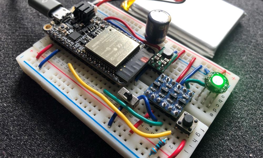
So, the diagram above is based on a breadboard I wired using jumper cables, so I know it works. Replacing the looped jumper wires with solid-core breadboard wire makes a big difference to the stability of the circuit. Using the power rails of the breadboard for 3v and 5v enables us to split the board into two areas, high and low voltage. We can measure the voltage, load and run a sketch before we start building anything permanent.
This is all working great!
1c Perma-Prototype
The Adafruit Perma-Proto boards are great for transferring breadboard circuits into prototypes as you just copy one from the other. However, this project is supposed to be easily customised so I don’t want to solder everything together.
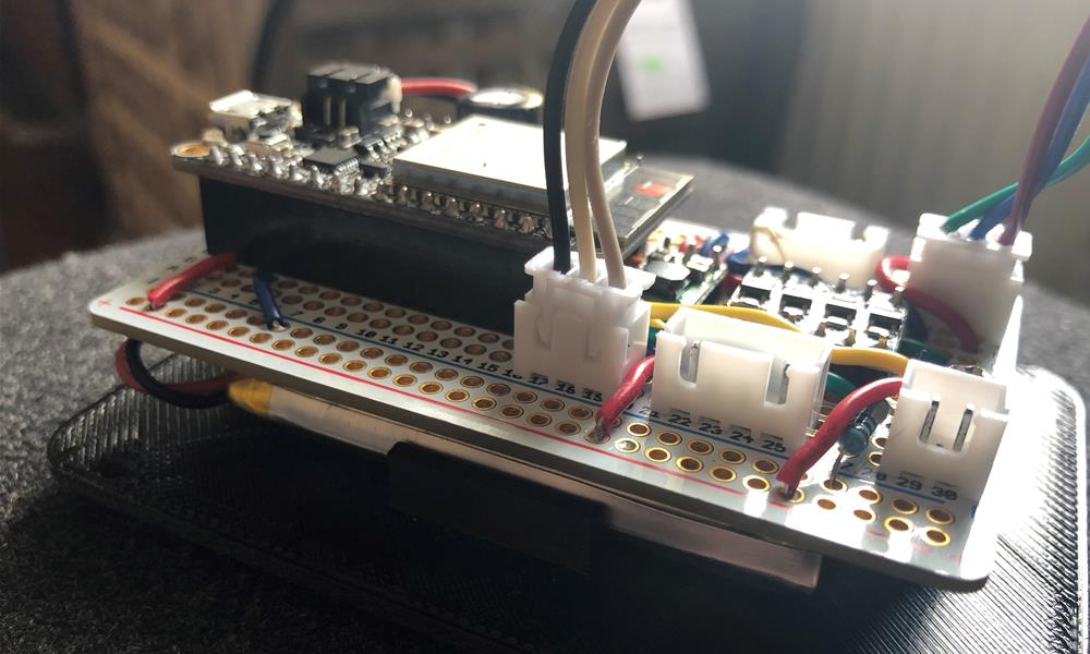
I’m going to use headers for the ESP, and JST (Japanese solderless terminals) Headers and Leads for external breakout components. This means if we want to change LEDs or i2c components we can just unplug them. The JST crimps come on a strip of 100 that usually get fed into a crimping machine, doing this by hand is fiddly and I’m at about 70% success rate after doing about 50 of them.
I have fat fingers and my vision isn’t what it used to be, this also makes soldering a challenge too. My favourite soldering hack is BlueTack. I use it to hold components in place and even to hold wires against terminals. It comes off easily but goes a bit soft while it is hot, wait until things have cooled down before removing it.
I now have a prototype board that you can chuck about safely, however, this is not rapid prototyping. With over 100 joins (and that’s after the pins have been soldered to the components) this takes ages and there is quite a bit off room for error.
Now we’re happy that everything works, let us start to streamline the process.
1d Custom PCB
If all that Fritzing did was help me create the diagram above that would be great, but it also makes the next step towards prototyping almost effortless.
From are Breadboard diagram we simply switch to the PCB tab, enter the size of the board, drag the components where we want them and press AutoRoute. I tidied up the traces to line up and created 1 sided and 2 sided versions of the board.
Export for Milling in the PCB tab will give us all the Gerber files required to mill the copper-plated board. These look great and soldering on milled board is OK. I would like more clearance on these than I have on my example, as the entire surface of the board is conductive making the potential for shorting far greater. We are only two slightly lumpy joins away from blowing the board.
The Fritzing Fabrication Service offers an alternative to milling boards and with the click of the button, I discover I can have two-sided PCBs with a silkscreen layer showing where the components sit, all for twenty quid. I’ve outlined this simple and rapid service in a Step-By-Step article.
Fritzing is a great software package and has helped me get my head around electronics. I created a component for the 5v Step-Up to go on my breadboard by altering an existing component and importing new SVG files. This feature doesn’t work correctly and as it only imports one copper layer, it doesn’t produce the correct output when producing PCBs.
The credit screen says ‘BETA’ but there is no evidence that it is still being worked on. This limitation means I will try AutoDesk Eagle for my next module.
1e Sensor Module
The idea of this device is that if I need it to perform different tasks, for example, record audio or measure movement, then the board remains the same and we just create a new breakout and a modified case.
Our current case has holes for the LED’ to shine through and a hole for the tactile switch, we don’t need to expose the sensor, it can live happily inside the case.
I already have ¼ Perma-Proto board screwed to the top of the case that houses the tactile switch, we’ll add another 4 terminal JST lead for the i2C connection and solder the sensor onto the board.
OK, we’re done wiring.
References
1. K. Beck, Extreme programming explained: Embrace change. (Harlow: Addison-Wesley, 1999), p85.
2. C. Fernandez-Gago, F. Moyano, J. Lopez, “Modelling trust dynamics in the Internet of Things”, Information Sciences, Volume 396, (2017), p72-82.
3. V.Gampala, S. Inuganti, S. Muppidi, “Data Security in Cloud Computing with Elliptic Curve Cryptography,” International Journal of Soft Computing and Engineering (IJSCE), Volume-2, Issue-3, (July 2012), p138.
4. A. Anand, A. Galletta, A. Celesti, M. Fazio and M. Villari, "A secure inter-domain communication for IoT devices," 2019 IEEE International Conference on Cloud Engineering (IC2E), Prague, Czech Republic, (2019), p235-240.
5. Espressif, “API Guides – Secure Boot”, Retrieved from https://docs.espressif.com/projects/esp-idf/en/latest/esp32/security/secure-boot-v1.html.
6. Espressif, “API Guides – Flash Encryption”, Retrieved from https://docs.espressif.com/projects/esp-idf/en/latest/esp32/security/flash-encryption.html.
7. K. Sovani, “Understanding ESP32’s Security Features”, Retrieved from https://medium.com/the-esp-journal/understanding-esp32s-security-features-14483e465724, (2013, October 1).
8. A. Inamdar, “ESP32-S2 — Security Features”, Retrieved from https://medium.com/the-esp-journal/esp32-s2-security-improvements-5e5453f98590, (2019, Dec 10).